

Fire Integrity
Fire integrity analysis of process systems
Legislation, standards, as well as company defined risk acceptance criteria, impose certain requirements on the design of process facilities regarding their ability to sustain a fire situation. We have developed tools and work methods to address these issues, and we have a long list of reference projects.
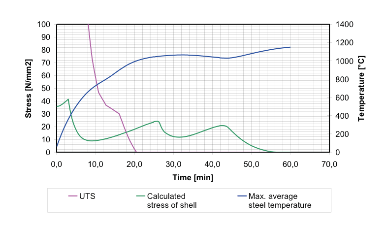
Fire integrity of pipework and equipment under pressure is a function of fluid characteristics, process conditions, materials, the presence of passive fire protection, blowdown and depressurization facilities. When a hydrocarbon fluid is heated, components will boil off in accordance with its thermodynamic properties, and the pressure inside will increase. The increased pressure will impose a higher load on the process equipment. As the material in pipework and vessels is heated, the material starts to lose its strength.
The required fire integrity of a process system is related to how long the system must keep the inventory inside the system to allow for safe escape and evacuation of personnel and to prevent escalation. This may be 15 minutes, or maybe 1 hour. VessFire is developed to assist engineers in ensuring that process plants have sufficient blowdown capacity and structural integrity (time to rupture) in defined fire scenarios. VessFire calculates blowdown rates in compliance with advanced methods put forward in ISO 23251:2006/API 521.
Fire Integrity of Flanges
The main hazard of an onshore or offshore oil & gas installation is leakage of flammable and/or explosive substances. Most leakages originate from flanges or fittings. The fire integrity of flanges is a major concern for preventing escalation of a fire.
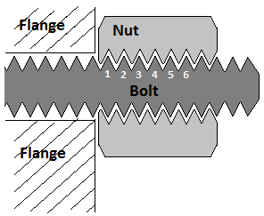
Bolts will easily lose their load-bearing capacity when exposed to heating; the bolts are subject to pre-tension, and the load is carried by the threads. When threads (bolt and nut) get heated sufficiently, the nuts will disconnect, and a leakage will occur.
Standards like NORSOK address the need for preventing leaks from clanges and connections (sec. 8.4.3 in S-001). In order to address this issue, we have developed a procedure for analysis of fire integrity of flanges. Based on a series of experiment at the fire laboratory at SINTEF (now: RISE Fire Research), the integrity of ASME WN flanges and compact flanges were examined, and 3D computer models were made in Brilliant. Our procedure for execution of fire integrity analysis of flanges utilise these models combined with VessFire analysis.
Software model
Petrell has several years of experience with modelling and simulation of flanges exposed to fire. Our software has been verified for ASME and Compact flanges in projects sponsored by Equinor.
Verification
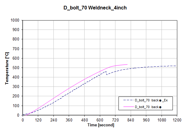
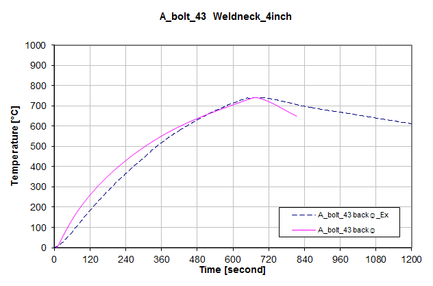
The methodology has been verified thorugh experiments performed at RISE Fire Research AS. The graphs below display temperature profile for the six innermost threads (bolt and nut) in a compact flange, both with and without passive fire protection.
Fire integrity of structures
Requirements regarding Passive Fire Protection (PFP) are found in ISO 13702 Petroleum and natural gas industries – Control and mitigation of fires and explosions on offshore production installation. Requirements and guidelines (Ch. 12 and Appendix B.9), as well as in NORSOK S-001. Onshore and offshore oil & gas installations shall be able to withstand the specified fire design accidental loads. This load is normally found in the installations risk analysis and/or in the Design Accidental Load specification.
The purpose of providing a structure with PFP is to ensure that it remains intact during the accidental situation sufficiently long enough to allow for safe escape and possibly evacuation of personnel, including adequate fire fighting actions. Determining whether a structural component (wall, ceiling/ deck, door, pipe support, bridge, etc.) has sufficient integrity in a fire situation is necessary before a recommendation regarding PFP can be made.
If initial results show that the component reaches the critical temperature too fast then PFP must be added until the component’s temperature history is deemed acceptable. This approach can also be used to optimise the amount of PFP to apply, and to evaluate the effectiveness of alternative PFP materials.
Do you want more information?
Please send us an enquiry, and we’ll be in touch as soon as possible. We always look forward to hear from you!
